Lab 8
Here are some stuffs for lab 8!
Overview
This lab is one of the shortest one (besides lab 6) so far.
Knowledge in magnetic field model is required.
Right Hand Rules are applied in most questions.
Warning
Due date is 3 days after lab days!
Concepts of Right Hand Rules
Explanation
Thumb points in the direction of the current and the fingers curl around the wire in the direction of the magnetic field.
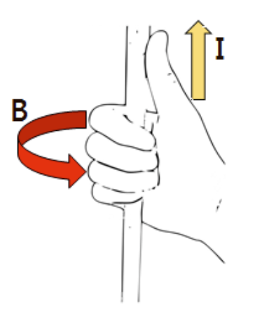
Fig. 30 Right-hand rule for current carrying wire
Explanation
Fingers curl in the direction of the current through the solenoid and the thum b points in the direction of the magnetic field.
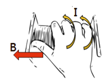
Fig. 31 Right-hand rule for current carrying solenoid
Explanation
Force on a moving positive charge in a magnetic field: Thumb points in the direction of the velocity (electrons are negatively charged and therefore point in the opposite direction), fingers point in the direction of the magnetic field and the palm faces the direction of the force on the charge. Other sources suggest to bend the middle finger inwards so that it points along the direction of the force vector. An alternate version can be read in lab manual.
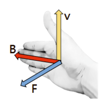
Fig. 32 Right-hand rule for moving charge in magnetic field
Part 1: Magnetic Field of a Solenoid
Before we go any further, lets look at the setup for this experiment:
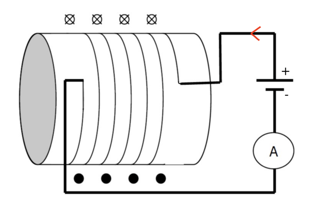
Fig. 33 Part 1 set up
Here, you are required to perform only 1 calculation with given the data below:
Data |
Value |
|---|---|
Magnetic Field Strength |
\(0.26\pm0.03\)(mT) |
Induced Current |
\(53.8\pm0.3\)(mA) |
The question is: What is the number of turns of wire per meter in the solenoid? Which formula will you use?
Error calculation is required, so make sure you do it.
Caution
Convert data into approriate units. Why? Check the units of your \(\mu_0\).
Part 2: Force on a Moving Charge in a Magnetic Field
Let’s consider 3 cases as in the manual.
Recall magnetic force is exerted only moving charged objects in the magnetic field.
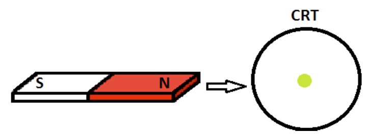
Fig. 34 Set up for case 1 part 2
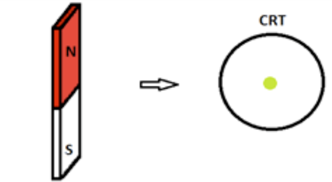
Fig. 35 Set up for case 2 part 2
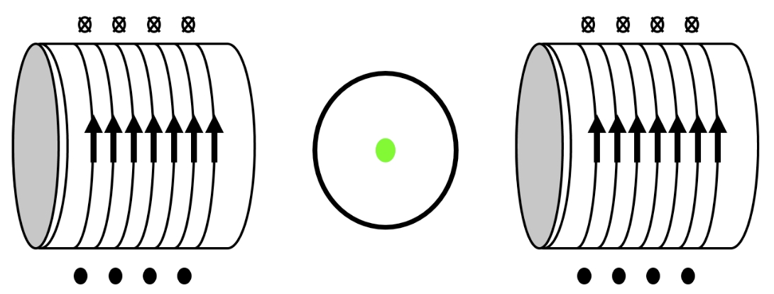
Fig. 36 Set up for case 3 part 2
See also
The electron beam is shot out of the page. That also means these electrons are moving. Bringing a magnet near the beam creats a magnetic field around this beam.
Task for each case includes:
Step 0: Only for case 3 (solenoid), use the solenoid version of right-hand rule to find magnetic field direction at the center of each solenoid.
Step 1: Use Right-hand rules for moving charges to identify the direction of the magnetic force on the electron beam.
Step 2: Describe how you would use Right-hand rules (detailed explanation of step 1).
Step 3: Draw the magnetic field created by the magnet. For solenoid, draw the magnetic field at its center.
Step 4: Draw the force direction on the picture (visualize your finding).
Part 3: Induced Voltages
This parts consists of 2 sub-parts (sections).
The second one involves working with oPhysics simulator (link in manual).
Section 1: Lenz’s Law
Restate the Lenz’s Law (relating flux) that you have learned in lecture.
You can be brief but include all essential information.
Note
If you like more details, why not? Time to revise!
Section 2: Experiment with oPhysiscs simulator
Either manually drag the magnet or automate the motion sinusoidally.
There are two cases:
Magnet moving inside the solenoid.
Magnet moving out of the solenoid.
For each case, do the following task:
Step 1: Follow each case to set the magnet moving accordingly.
Step 2: Record the direction of the current (Red arrow >). Picture in report sheet is similar to simulator setup.
Step 3: Use the current direction to figure out sign of the galvanometer’s readings.
Tip
If you are confused in how to transfer current direction from simulator to report sheet, use right-hand rule to get your result.
Part 4: Explore
You can have fun with another online simulator. In this case, it is a loop rotating in a magentic filed created by 2 magnets.
There are no questions about this part. So, just have fun!
Note
oPhysics is one of the most popular websites with amazing simulators. For anyone in physics-related major, I would reccommend taking time playing with it!
Discussion
Notice there are 2 last conceptual questions that you need to infer from observations.
Galvanometer’s readings sign: Find direction of induced current
Current goes into + terminal <=> readings are positive
Current goes into - terminal. <=> readings are negative
Brightness of light bulb: Try a higher speed in the simulator
Intensity/Brightness is the power per unit area. Now, assumed we look at the bulb at a fixed distance.
Power in electric circuit model: \(P = \frac{\epsilon^2}{R}\)
\(\epsilon\) is the induced potential difference, which has a formula \(\epsilon = |\frac{d\phi_m}{dt}|\).
Tip
\(\frac{d\phi_m}{dt}\) is the change in flux over a surface area.